dMix 128 Reference Manual
A 128-channel digital mixing console with web-based control. This guide walks through every screen of the GUI in the order you'll meet them — from first connection to scene recall — with annotated diagrams of each view.
Contents
- Connecting to the mixer
- Mixer Password
- The main mixer view
- Channel strip & signal flow
- Preamp Page
- Input Source
- HPF and LPF Filter
- Parametric EQ
- Dynamic EQ
- Compressor
- Gate
- De-esser
- Multiband compressor
- Graphic EQ
- Aux sends
- FX Sends
- FX rack
- FX - Standard REVERB
- Delay
- Chorus
- DX480 Reverb Engine
- Routing - Inputs
- Routing - Outputs
- Copy Channels for monitor split
- Cascade assign channels
- Soundcheck Mode
- DCA, SUB, mute & view groups
- DCA Remote Faders
- Sub Groups
- Matrix Mixing
- Shows & snapshots
- Scene Isolation
- Overview Page
- Presets
- Oscilator
- Shortcut Keys
- Adding Network devices -1
- adding devices -2
- Ui Page
- Processing usage
- Solo
- About
- Firmware update & Recovery Options
Connecting to the mixer
Topology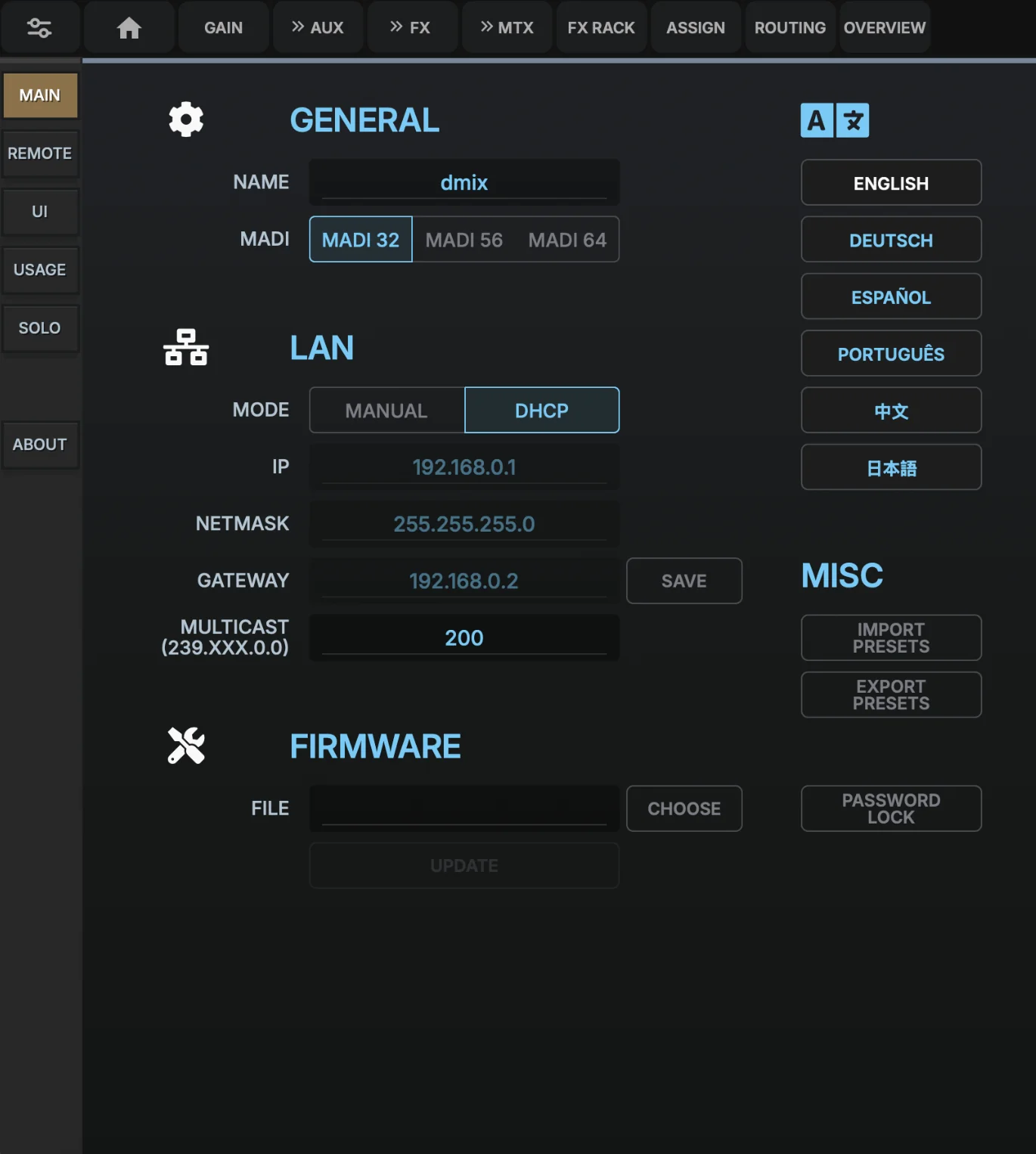 123456
- Open the GUINavigate any browser to the mixer's name (dmix.local by default) or the IP address (e.g.
http://192.168.1.50) on port 80. For information about finding the IP address refer to the reference guide. - Name your unitChange the name of the unit so it can be called via DNS naming (default is dMix.local)
- MADI clock selector Select MADI options between MADI 32/56 and 64, the dMix128 has built in SRC's ensuring the incoming and outgoing signals always match the selected rates.
- Language selectorSelect the language you feel most comfortable working with, let us know if you want a new one added.
- Firmware UpdateClick the firmware update button to open the call out page for this function.
- Import/Export presetsOur website will have a large amount of channel and processing presets available to download, you can also save and share your own. It's a great community to be a part of.
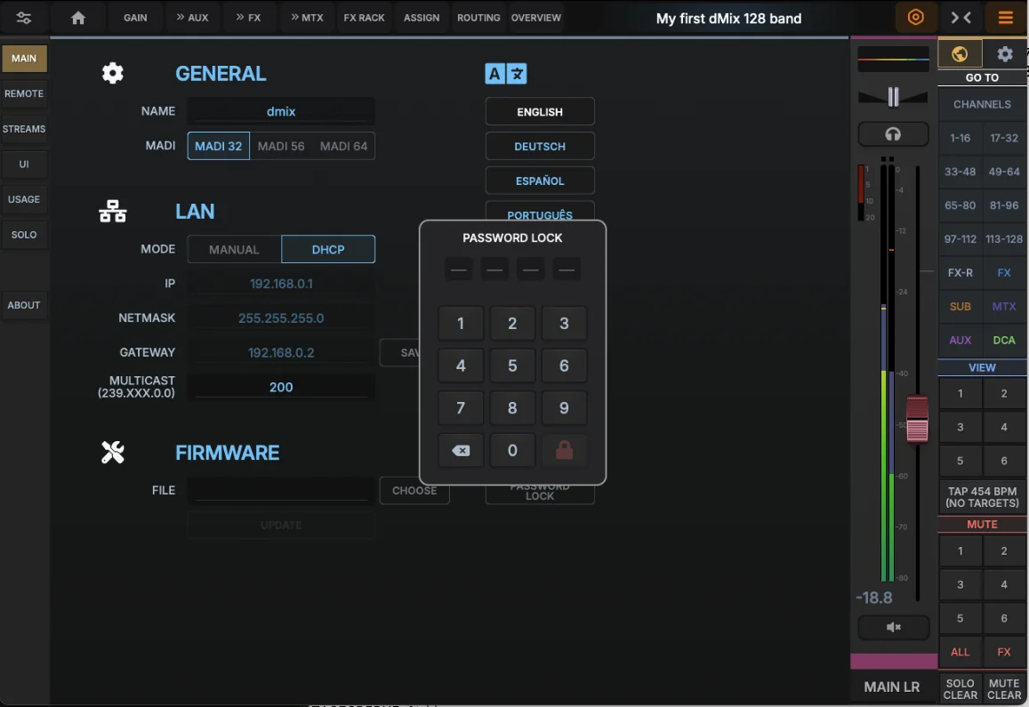
- Password LockAdd a 4 digit password to the dMix128, please remember it, we don't have any magic dust to guess what you added.
- Lan interfaceGigabit Ethernet provides the fastest, most reliable connection for studio setups. Use DHCP for automatic IP assignment or configure static IP for integration with larger audio networks and recording systems.
- Web interfaceThe built-in web server hosts the complete mixer interface. Access via IP address or the friendly
dmix.localhostname. mDNS and UPnP make device discovery automatic on most networks.
On first connection the GUI shows the Default show with a blank snapshot. Save your work as a new show before tuning so the factory default stays clean.
Mixer Password
If a password is needed for the Mixer, enter it here. It's a 4 digit number. Please store it somewhere. This is your responsibility to remember.
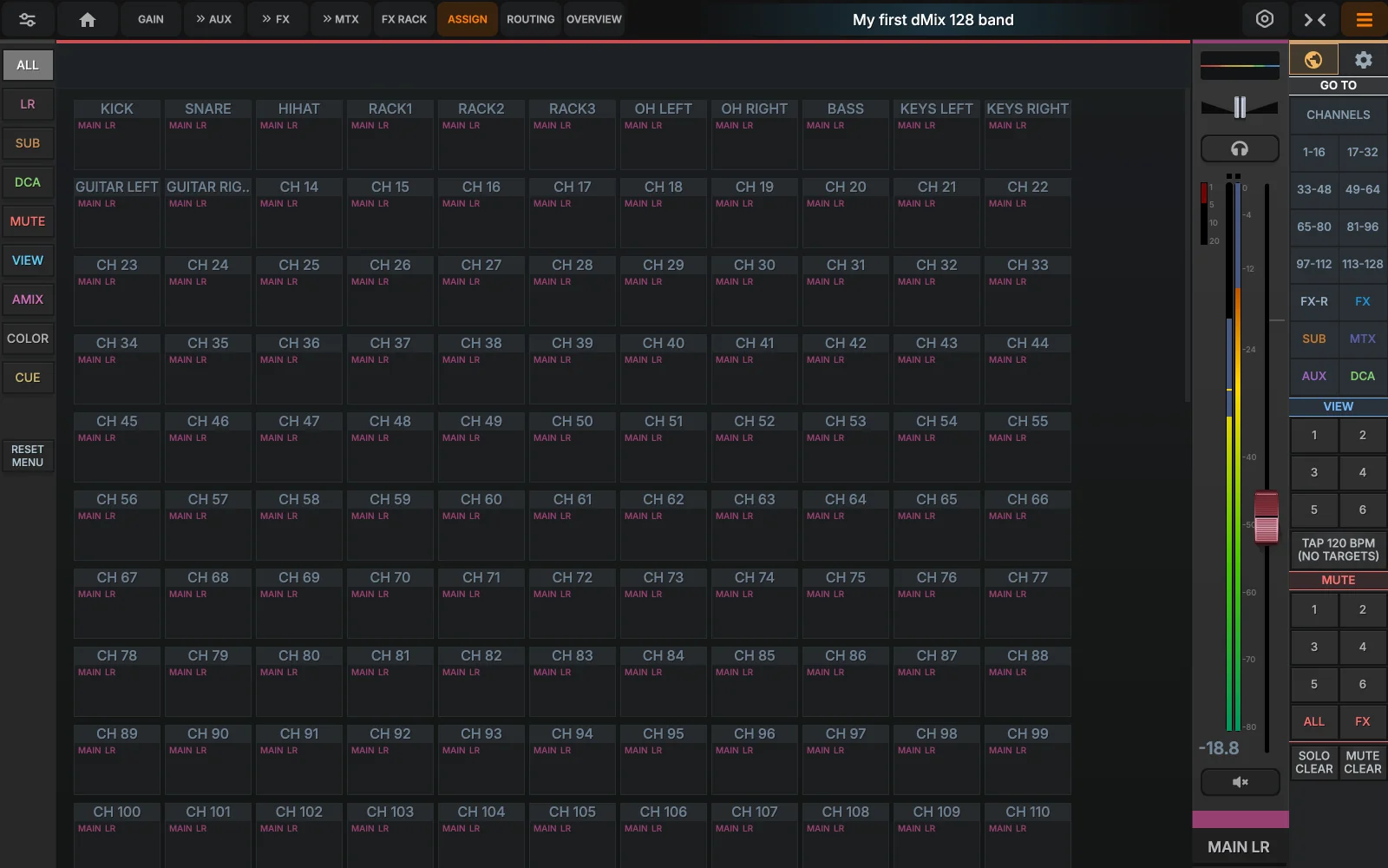
The main mixer view
This is the screen you'll spend most of your time on. Every input, bus and master strip lives here, organised into layers you can flick between. Tap any strip to select it for processing; tap the strip header to open its full channel view.
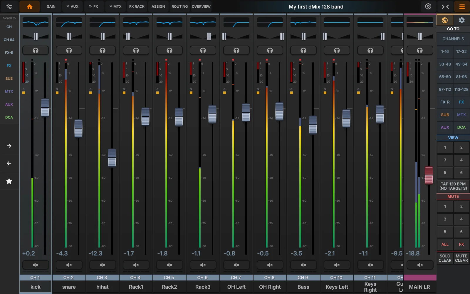
- Status barCurrent show & snapshot, Solo and Mute states. Tap show or snapshot fields to open the recall browser.
- Layer / bank tabsSwitch between CHANNEL VIEW, CHANNEL page (HOME),GAIN, AUX, FX, MATRIX MIXER, FX RACK, ASSIGN, ROUTING and OVERVIEW pages- These are all SEND, full mixer pages.
- Channel informationTap hold or Mouse hold the channel name plate to rename, re-color or open full channel processing. The CH number and preamp gain are shown below.
- Left PanelChannel Mode (input channels),JUMP- to Channel 64, FX-Return Masters, FX Send Masters, Subgroup masters, Matrix Masters, AUX Masters, DCA Masters- (These buttons are all JUMP sections of the main mixer layout)- BANK LEFT and BANK RIGHT on GUI, HOT CHANNEL selector.
- Settings pageEnter settings pages, Network, connectivity to AES67, GUI settings, Security.
- Channel SqueezeFit more channels on the screen at the same time
- Right PANEL ExtenderSwitch the right panel ON or OFF to extend the MIX area
- Select GUI Navigation or Special FunctionsSelects the Side panel to view GUI Navigation or Special functions such as switching to SOUND CHECK mode, Turning on the Oscillator, Fast Snapshot recall.
- GOTO section - CHANNELSDrag your finger across the CHANNELS button to navigate quickly between all 128 channels.
- GOTO section - Fader BansJump to Fader Bank channel sections
- View GroupsHold view group button down to enter Assign mode or use the Assign menu to program the view groups (they are PER GUI that's used, not global)
- TAP TEMPOGlobal Tap Tempo button
- MUTE GROUPS and CLEAR BUTTONSHOLD Mute Group Button to enter Assign mode or use the ASSIGN page to program the Mute Channels that you want to save in the group, this is a GLOBAL button. It effects all users.
- HOT channel and Bank moveSelect a channel and hold down the STAR( HOT CHANNEL) button, the GUI will navigate to this channel when ever the STAR is now pressed. Depending on the screen size and the channels shown the BANK LEFT / BANK RIGHT arrows and navigate the channels on the screen by Bank.
- EQ ViewA general view of the EQ applied to the channel, Click on the EQ to bring up a full EQ edit page.
The top menu is mainly for channel levels and sends, the Left panel is mainly for MASTERS, The Right panel is mainly for Navigation.
Channel strip & signal flow
Every input channel runs through the same processing chain. The order of the blocks marked in amber is reorderable per channel — gate, comp, EQ, de-esser, multiband and graphic EQ slots can all be re-arranged in the channel-flow editor (parameter .flow).
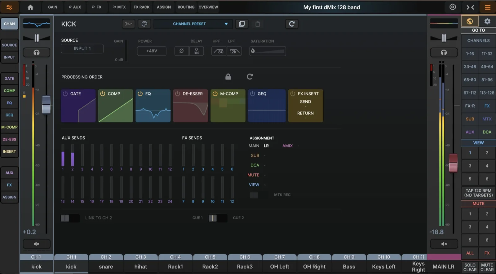
- Source & preampPick the physical input (analog, AES, MADI, expansion, network or DAW) and set preamp gain. The hardware gain stage is shared with any channel that uses the same input.
- Pre stageTrim when Digital input is used (±24 dB), Gain when analog input is used, phase invert, phantom power, channel HPF and per-channel delay (0–250 ms) are always at the head of the chain.
- Reorderable processingGate, compressor, EQ, de-esser, multiband, graphic EQ and insert can be dragged into any order. Press the Unlock button and re-order the processing in real time.
- Fader & panChannel level and pan after all processing. The fader feeds the master and any post-fader sends.
- Sends & bus assignment24 aux sends + 8 FX sends per input. Each send can be tapped pre-EQ, pre-fader or post-fader. Channels are simultaneously routed to the master, sub-groups, VCAs and matrix.
- Cue Bus assignemntsCue bus 1 or 2 selection
- SaturationAdd Harmonic distortion/ Saturation to the channel.
- Channel LinkFor Stereo inputs, link to the next channel (odd to even or even to odd are allowed)
- View Channel AssignmentsView all the channel assignments for the selected channel
If you've got a fixed FOH chain you like (e.g. gate → EQ → comp), set it once on a single channel, then save it as a channel preset and apply across the rest of the band.
Preamp Page
Input · CH 09 · Lead Vocal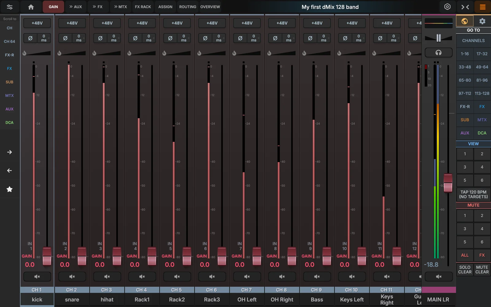 1234
1234
- Preamp gainCoarse analog gain, upto 55 dB. Drives the front-end before any digital processing. Long hold on the fader cap to enter a precise dB value.
- +48V · ø · Delay, SaturationPhantom power, phase invert and Delay plus Saturation
- TrimFine digital trim ±24 dB, applied after the preamp and used to keep the same channel level when shows have different gain structures. It will show up when a Digital Input is selected
- Name, color, channel assginmentsHold Down the Channel NAME for 2 seconds to Rename the channel and pick one of eight chassis colors used everywhere the strip appears.
Input Source
Select where the channel input is being sent from. This can be from any connected device, another dMix128, Computer, MADI or the option card. By default the input will come from the Front Panel XLR connection.
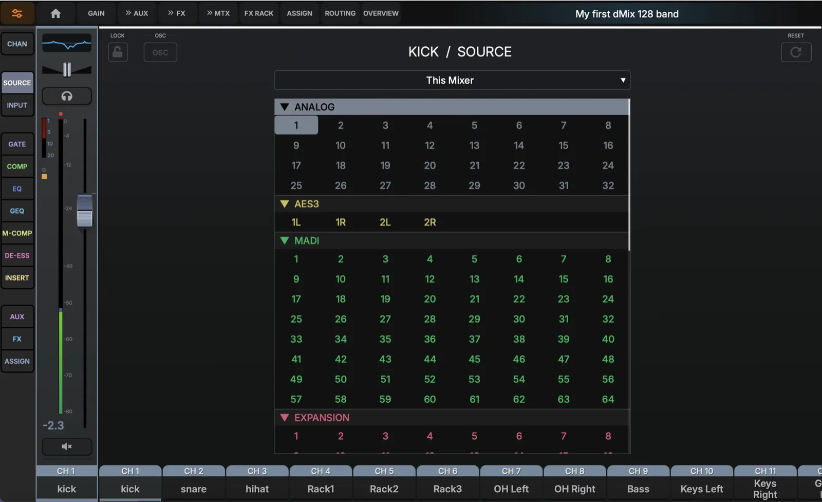
- Unlock Press unlock to enable routing of the input
- Select the Mixer If on a network with multiple devices, input can be selected from Any device.
- Turn on OscillatorFor testing purposes the oscillator can be turned ON for any channel, both input and output.
- Scroll barScroll down to select other input options.
When selecting a Digital INPUT, the GAIN control will turn into a TRIM control.
HPF and LPF Filter
Independent high- and low-pass filters with selectable slope (6 / 12 / 24 dB/oct). Drag the handles on the left and right edges of the curve.
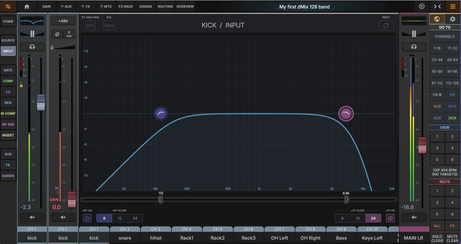
- HPF / LPF ONTurn ON processing for HPF and LPF
- Select Slope range6/12/24 dB per octave
- Adjust FrequencyMove the Frequency handle to match the Frequency you and wanting to set.
- Turn RTA/HOLD on/offSwitch the RTA On/Off as well as the HOLD function.
- ResetReset all settings to Default
Parametric EQ
A 4-band parametric EQ with dedicated HPF and LPF lives on every input, bus and master strip. Each of the four mid-bands can be shaped as bell, low/high shelf or notch; the outer bands can also become high-pass / low-pass for surgical cleanup, any of these bands can become a Dynamic EQ with Side chaining. Up to 4 more Parametric EQ's can be added to each channel. (from a pool of 128 Parametric EQ's)
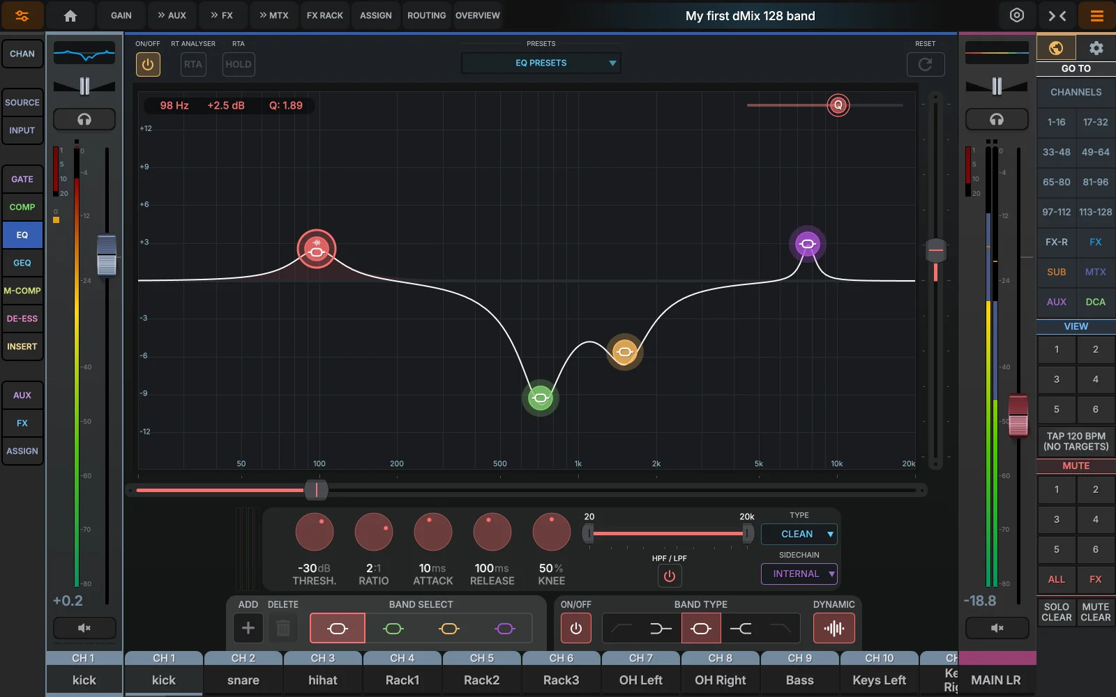
- Curve displayDrag any band's dot to set frequency & gain in one gesture; pinch (or scroll) to widen/narrow Q. The shaded area is the resulting transfer function.
- Active bandTap a band to select; its row in the parameter table highlights, and the on-screen handle becomes adjustable from the side controls.
- Band parametersTYPE (BELL / L-SHELF / H-SHELF / NOTCH / HPF / LPF).
- Toolbartoggle the RTA overlay (live spectrum behind the curve).Enable EQ overlay, then boost or cut EQ bands while watching the spectrum. You can see exactly which frequencies you're affecting and verify that problem frequencies are actually reduced. Use FREEZE to capture a problem moment for detailed analysis.
- Q valueChange the Q band Value, (use can also use PINCH on touch screens)
- FrequencyChange the frequency of a selected band. (or move the selected band by holding it down with a MOUSE/TOUCH)
- GainChange the Gain of a selected band. (can be done by holding a MOUSE left click Down on a band or Touch)
- Add EQ bandsUp to 4 extra bands can be added to any input or output channels/busses.
- Turn on Dynamic EQEach of the 4 main bands can have Dynamic EQ turned on
Up to 128 extra bands can be active across the whole console (4 bands per every input/output are already present by default). The EQ counter in the top utility bar shows current usage; if you hit the cap, deactivate EQ's on bands that are not pulling their weight. The resource manager can show you where all the extraEQ's are being used.
Dynamic EQ

- Dynamic toggleSwitching DYN ON converts the band into a compressor that acts only at the band's frequency & Q.
- ThresholdLevel at which the band starts working (–80 to 0 dB, measured at the sidechain). A dotted line on the curve shows the threshold.
- Ratio & rangeRatio sets how aggressively the band moves; the gain knob now caps the maximum reduction or boost.
- Attack / release0.5–500 ms attack, 10–2000 ms release. Faster on percussive material, slower on vocals.
- Sidechain sourceBy default the band listens to its own audio, but you can route any other channel into it — e.g. ducking the keys when the vocal sings.
- Sidechain filtersOptional HPF/LPF on the sidechain so the detector only hears the relevant band of the source.
- Compression typeSelect between CLEAN/VCA/FET
- Gain reduction in Dynamic EQShow the amount of Gain reduction occurring on a specific Dynamic EQ.
Up to 128 dynamic bands can be active across the whole console (res.dyneq). The Dyn EQ counter in the top utility bar shows current usage; if you hit the cap, deactivate DYN on bands that are not pulling their weight. The resource manager can show you where all the dynamic EQ's are being used.
Compressor
A four-flavor compressor sits on every channel and bus: Clean (transparent feed-forward), VCA (punchy bus character), FET (aggressive, fast), and Opto (smooth, program-dependent). Two heritage models — DNA22 and DNA34 — emulate vintage hardware curves.
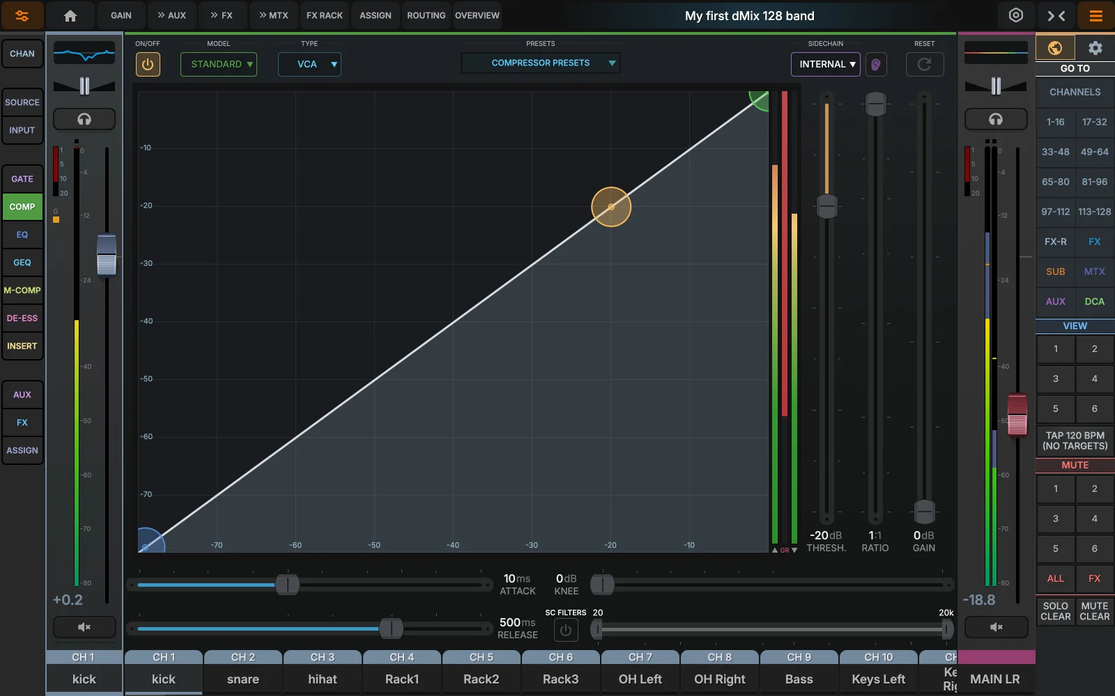
- Compressor flavorClean / VCA / FET / Opto change the detector and ballistics. DNA22 and DNA34 add additional vintage curves on top.
- Transfer curveLive representation of input vs output. Threshold and ratio are reflected here as you turn the knobs.
- Live GR readoutNumerical gain-reduction in dB plus a vertical bar — same data also feeds the comp icon on the channel strip.
- Threshold & ratioThreshold –80 to 0 dB, ratio 1:1 to 20:1.
- Make-up & kneeUp to +24 dB make-up, knee soft/hard or 0–60 dB continuous.
- Hold · Limiter · PickupHold prolongs gain reduction; limiter caps the output; pickup chooses where on the chain the comp listens (PRE-EQ / POST-EQ).
- SidechainPick any other channel as a key, optionally band-limit with HPF / LPF, and SOLO-listen to the key signal to set threshold.
- I/O meteringContinuous IN, OUT and GR meters along the bottom — useful for matching gain so the bypass A/B is fair.
Gate
Gate · CH 02 · Kick Out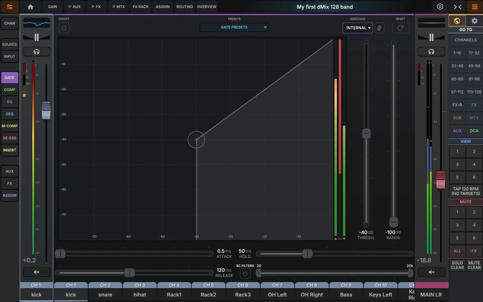 1234567
- On / offMaster bypass. The gate icon on the strip lights amber when the gate is currently closing (reducing gain).
- ThresholdWhere the gate opens (–80 to 0 dB). Drag the dotted line directly on the transfer display to set.
- Live stateOPEN / HOLD / CLOSED indicator updates in real time so you can dial threshold without ear-dialing first.
- Threshold / DepthThreshold is the trigger point; depth (range) is how far the closed signal is attenuated, –90 to 0 dB.
- Attack · Hold · Release0.05–500 ms attack, 0–500 ms hold (keeps gate open), 5–4000 ms release for a smooth tail.
- SidechainUse the kick-in mic to gate the kick-out, or any external source. LISTEN solos the sidechain.
- Side Chain FiltersTune the input frequency to trigger the gate as needed.
Adjusting the Side Chain Filters will give you better performance for the gate. IE, Kick drum- trigger from Mainly Low End
De-esser
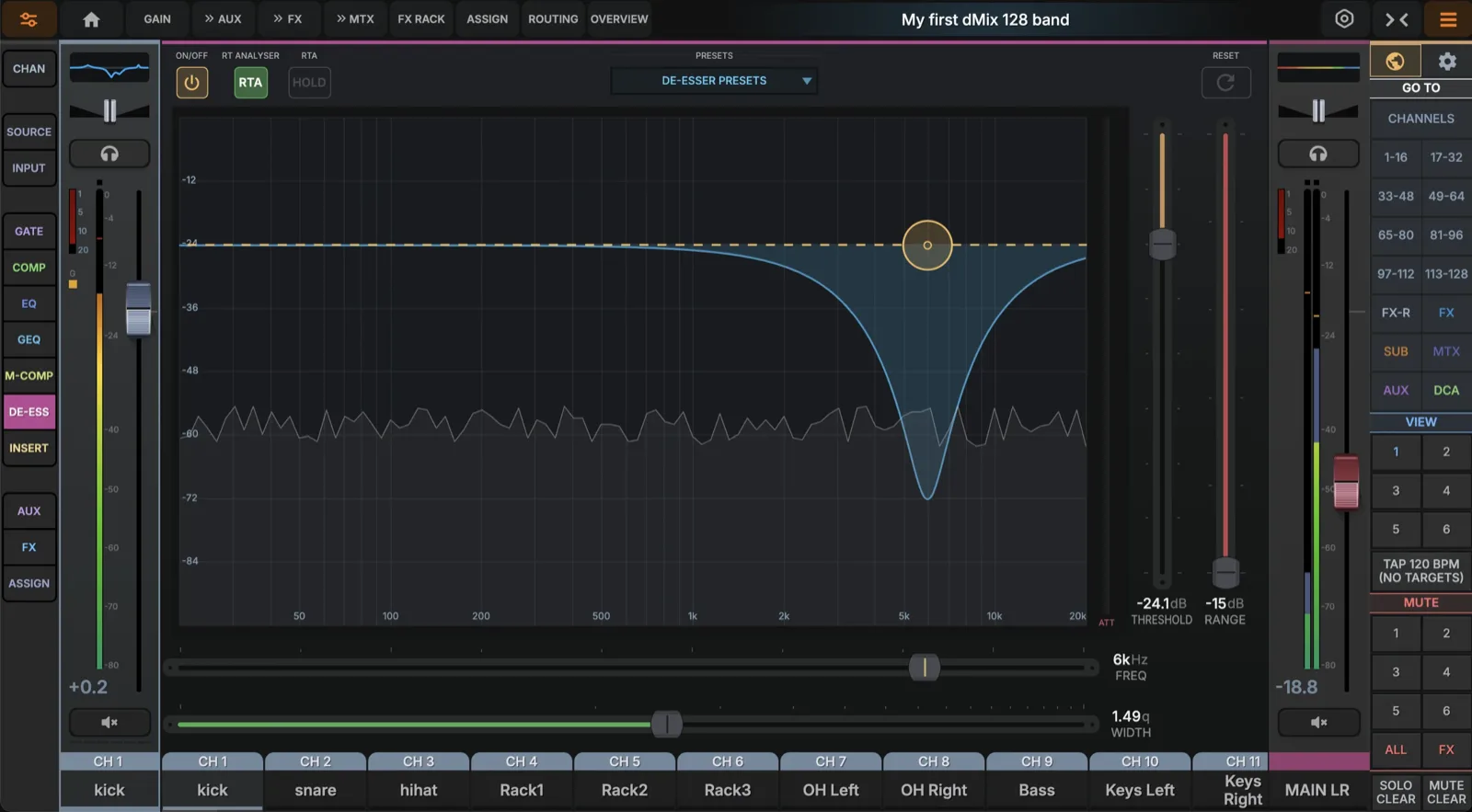
- FrequencyCenter of the de-essing band, typically 4–10 kHz on vocals. Drag the marker on the spectrum to set.
- Q / widthHow wide the band reacts. Narrow (high Q) for a single resonance; wide for general "tssh" reduction.
- ThresholdLevel above which sibilance is reduced. Drop until you hear it working on the worst esses.
- RangeMaximum gain reduction the de-esser can apply. –9 to –12 dB is a common ceiling.
- RTAClick on the RTA and easily see where the eSS's are occurring, a very easy way to visually see and remove.
- ATTShows real-time attenuation; aim for occasional flickers, not constant gain attenuation.
Multiband compressor
A 4-band multiband compressor for masters, drum buses, or stems where one full-band compressor pumps the whole signal, a multiband compressor can be used to specifically select frequency bands to compress. Each band has independent threshold, ratio, gain and ballistics. An overall side chain is available as well.
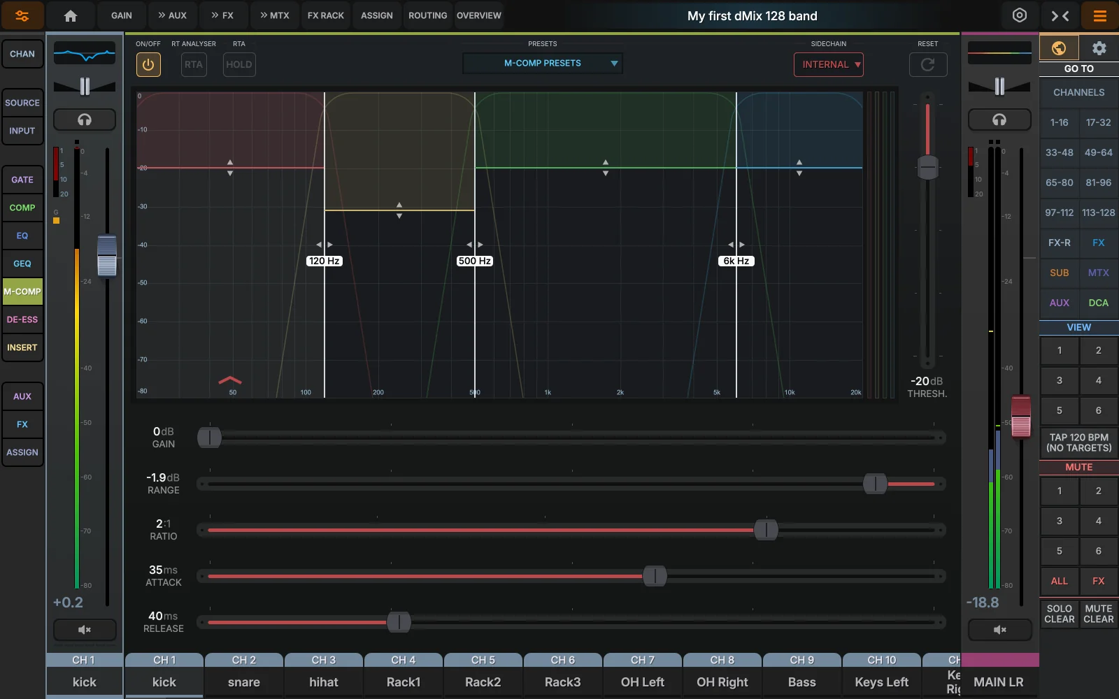
- Band threshold and displayDrag the band colours up/down to set per-band threshold. Click any band to focus its parameter row.
- CrossoversThree crossovers split the spectrum into 4 bands; drag the dotted lines on the display or enter values numerically.
- Live gain reductionDisplays the gain reduction per band in real time.
- RTA and HoldFull RTA display and HOLD.
- Per-band dynamicsEach band has its own threshold, ratio, gain, attack, release and range — same parameter set as the wide-band compressor.
- SidechainSelect a SideChain channel/AUX/Subgroup to control the input to the threshold of the multi band compressor.
The console allows up to 24 multiband compressor instances total (res.mcomp). The header shows usage; if a snapshot recall would push you over, the lowest-priority instance is auto-bypassed and flagged with an amber dot.nThe full list or resources can be shown in the resource manager in the setting pages.
Graphic EQ
A 31-band, 1/3-octave graphic EQ available on every aux, sub, master, return and matrix bus. Use it for room tuning on monitor sends or master, or for a quick broad-strokes correction without committing parametric bands.
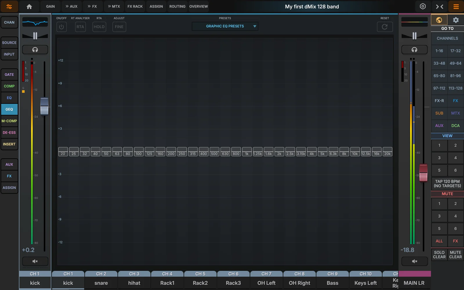
- 31 sliders1/3-octave bands from 20 Hz to 20 kHz, ±12 dB each. Drag a slider; double-tap to flat that band.
- Combined responseThe shaded amber area shows the cumulative effect of all sliders. Useful when ringing out monitors — pull a notch and watch the area dip.
- Frequency labelsStandard ISO third-octave centres. Shortened on screen (1k2 = 1.25 kHz, etc.) — see ANSI S1.11 for the full series.
- RTA / FLAT / ONToggle a 1/3-oct RTA overlay behind the sliders, flatten the EQ in one tap, or fully bypass the GEQ block.
Up to 12 GEQ instances can run simultaneously across the console (res.geq). Disabling a GEQ frees its slot — useful when you only need one for a stage monitor.
Aux sends
Each input channel can feed up to 24 aux buses (typically monitor mixes). Sends are tappable pre-EQ, pre-fader or post-fader, with optional pan-follow for stereo aux feeds.
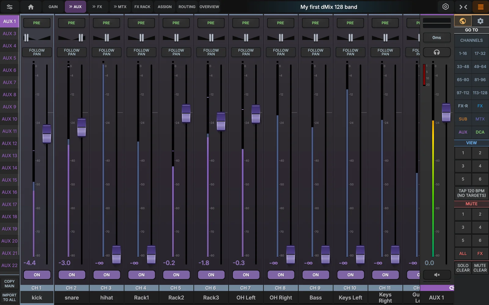
- Aux send cellEach cell shows aux number, bus name, send level (numeric + bar), and the tap point. Drag the bar to set the send; double-tap to mute.
- Stereo aux follow-panWhen the destination is a stereo aux (paired buses), enabling PAN on the cell sends the channel's pan to the aux as well — perfect for stereo IEMs.
- Pre-fader sendsPre-fader sends (typical for monitors) ignore the channel fader — pulling the FOH fader doesn't pull the IEM mix.
- Mute channelMute the channel in the specific AUX you are controlling.
- AUX selectSelect the Aux send you want to control, a STEREO Aux send would use 2 sends linked.
- Link AUXe's, Aux delay, NAMINGPRESS AND HOLD to open a menu which allows you to link Aux sends (odd to even or even to odd), NAMING, Colouring etc).
- Copy MixCopy an AUX mix
FX Sends
12 stereo FX buses (reverb, delay…). Sends are tappable pre-EQ, pre-fader or post-fader. 10 of the FX sends are build in processors, 4 of them are HIGH END FPGA based dx480 reverbs with the other 6 spread across room reverbs, chorus/doublers and delays.
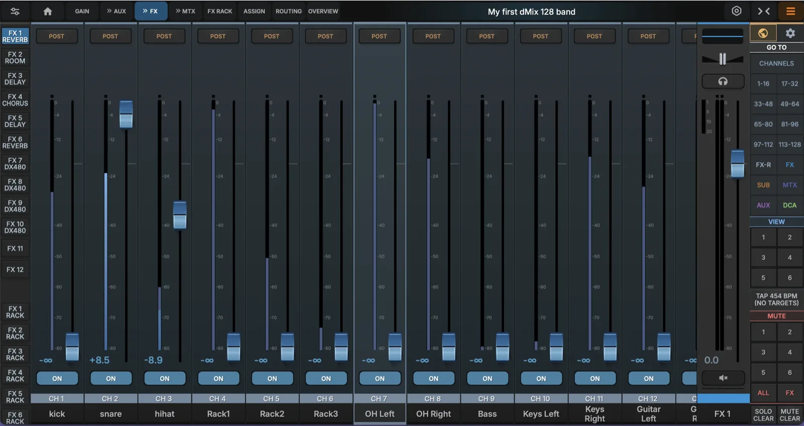
- FX Send selectSelect the FX Engine Send Level.
- FX Return SelectSelect the FX engine Return Level
- FX Master MuteMute button and FX master level
- FX Master EQ, PAN and SOLOEq indication the FX master Bus and solo button selector
- Pre Post FX send Select per channel PRE or POST channel FX send
FX rack
Ten mono/stereo FX slots host five different engine types. Slots are fed from any of the 10 FX sends and return to a dedicated Return channel for further EQ, dynamics, and routing.
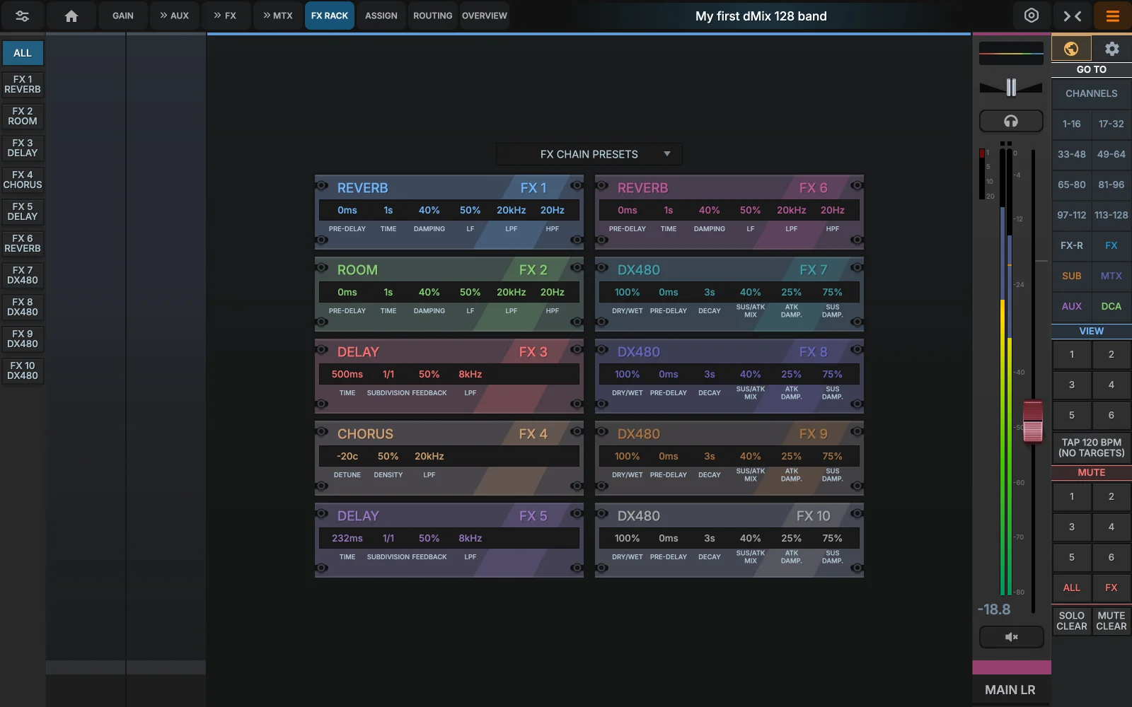
- Slot labelEach slot has a name (rename via the channel header) and a status pill. Slots can be soft-bypassed for instant before/after.
- Engine EditClick or Tap the FX Engine to edit the FX.
- Engine rowThe five engines available: Reverb (large halls), Room (small/medium spaces with strong early reflections), Delay (tap-tempo stereo with feedback), Chorus (LFO-modulated detuning), DX480 (multi-tap effects).
Every FX slot lands on a corresponding Return channel (R 1–10) which has its own EQ, dynamics, sends and routing — meaning you can EQ a reverb, compress a delay, or even feed an FX return into another FX send for cascaded effects.
FX - Standard REVERB
Select between Hall and Reverb algorithms.
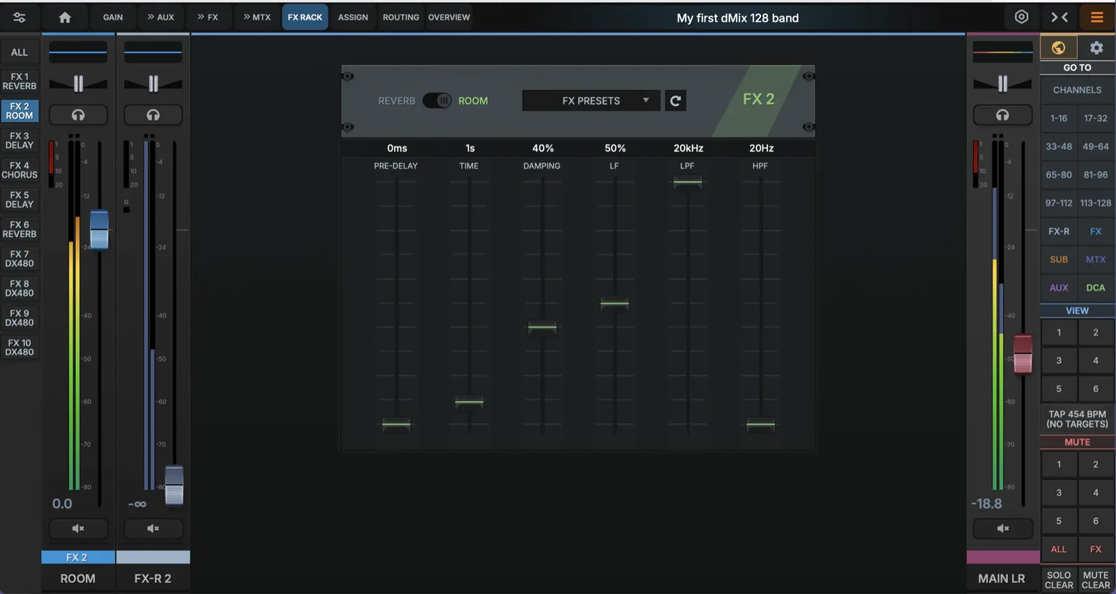
- Algorithm selectSelect between HALL reverb and Room reverb Algorithms.
- Pre delayHow Long before the reverb starts after the original sound. More pre-delay keeps vocals or instruments clearer and more forward sounding.
- Reverb TimeHow long the reverb tail lasts. Short time sounds like a small room; long time sounds like a hall or catherdral
- DampingReduced the high-frequency energy as the reverb decays. More damping makes the reverb darker and smoother.
- LFControls the Low-Frequency part of the reverb. Too much LF can make the reverb sound muddy or boomy.
- LPFLow Pass Filter, cuts high frequencies from the reverb. Lower LPF = Darker, Warmer
- HPFHigh Pass Filter, cost low frequencies from the reverb. Higher HPF = Cleaner reverb with less rumble.
Delay
This processor allows you to select between Delay and Chorus, the delay tempo can be assigned to a global tap which is present on the front page and can be controlled from external controllers as well.

- Algorithm selectDelay or Chorus selection for this Engine.
- TimeThe delay length, how long after the original sound will the echo be heard.
- SubdivisionSets the delay timing in Musical values, usually synced to tempo, for example 1/4 note, 1/8th note, dotted etc.
- FeedbackHow much of the delayed signal is fed back into the delay again, More feedback = more repeats.
- LPFLow Pass Filter, cuts high frequencies from the delay repeats. Lower LPF makes the echo softer so it sits better behind the original sound.
Chorus
This processor allows you to select between Delay and Chorus, The Chorus Effect can make it sound like two or more performers are playing or singing together. It works by copying the original signal, then adding a very small delay/pitch movement. You will get a Wider, Richer, slightly moving sound. It can make vocals, guitars, keys or pads feel bigger and smoother.
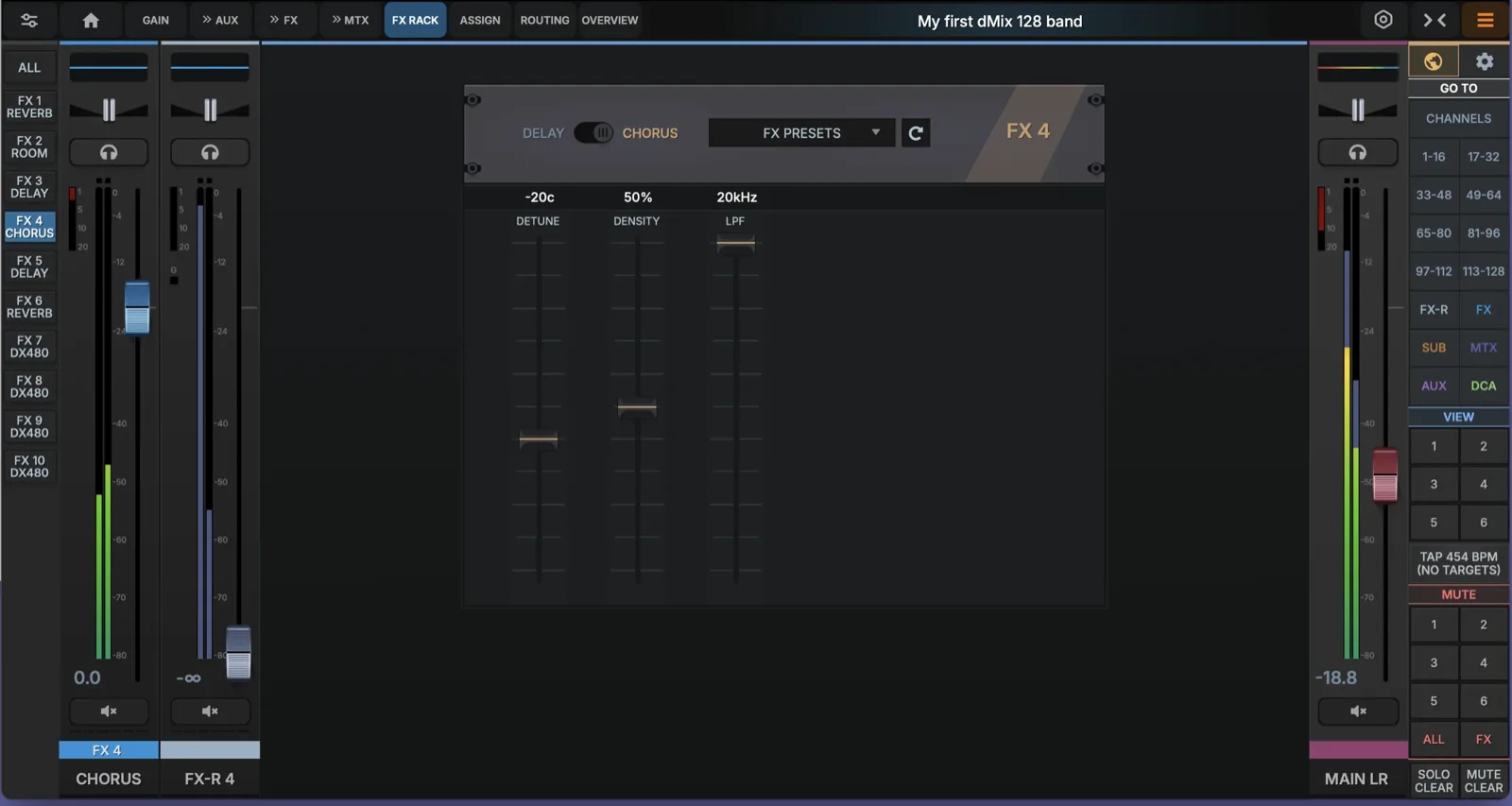
- Algorithm selectSelect between Delay and Chorus
- DetuneAdds a small Pith difference between the original sound and the chorus voices.
- DensityControls how many chorus voices or layers are created. Higher density sounds smoother and wider.
- LPFLow Pass Filter, cuts the high frequencies from the Effect helping sit behind the original sound.
DX480 Reverb Engine
This premium Algorithmic reverb focuses on sonic transparency and flat spectral response to eliminate unwanted metallic resonance while preserving the original signal's clarity. By separating the processing of initial transients from the decaying tail, the technology ensures Spatial Depth without introducing clutter into a professional mix.
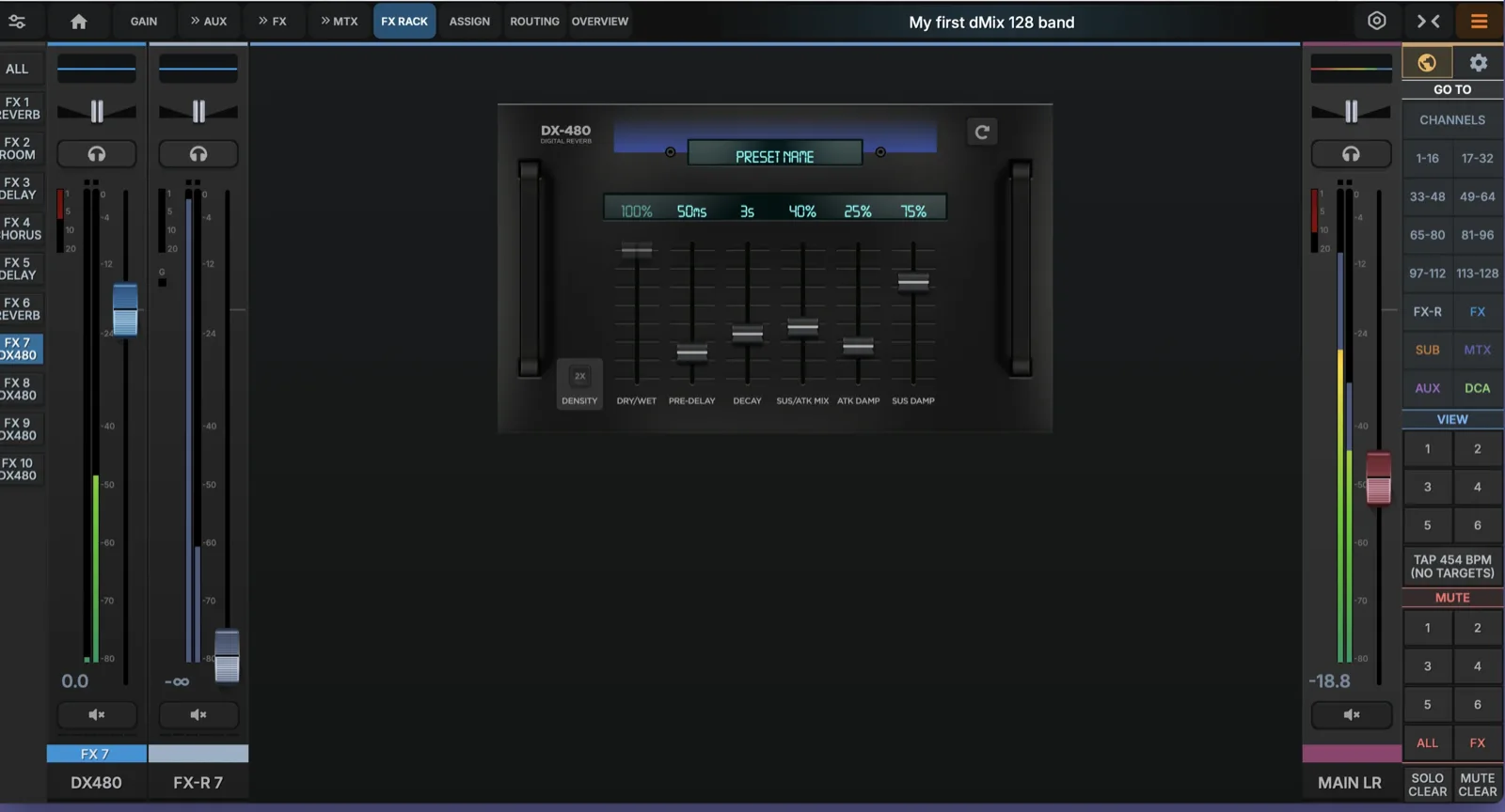
- Density and Dry/Wet settingPre set to Maximum as other parameters are already there to adjust these settings.
- Pre DelayHow Long before the reverb starts after the original sound. More pre-delay keeps vocals or instruments clearer and more forward sounding.
- DecayReverb time
- Sustain/Attack MixThe mix between the fast initial Reverb and the decay part, you can have a louder start and a software tail, for example for a snare drum, while for vocals use a longer tail sound.
- Attack DampingControls how quickly the reverb's bright/high-frequency energy builds up. More attack damping makes the revery start softer and less sharp.
- Decay DampingControls how quickly the high frequencies fade away during the revery tail. More decay damping makes the reverb sound darker as it fades, like a room where high frequencies die out faster than the lows.
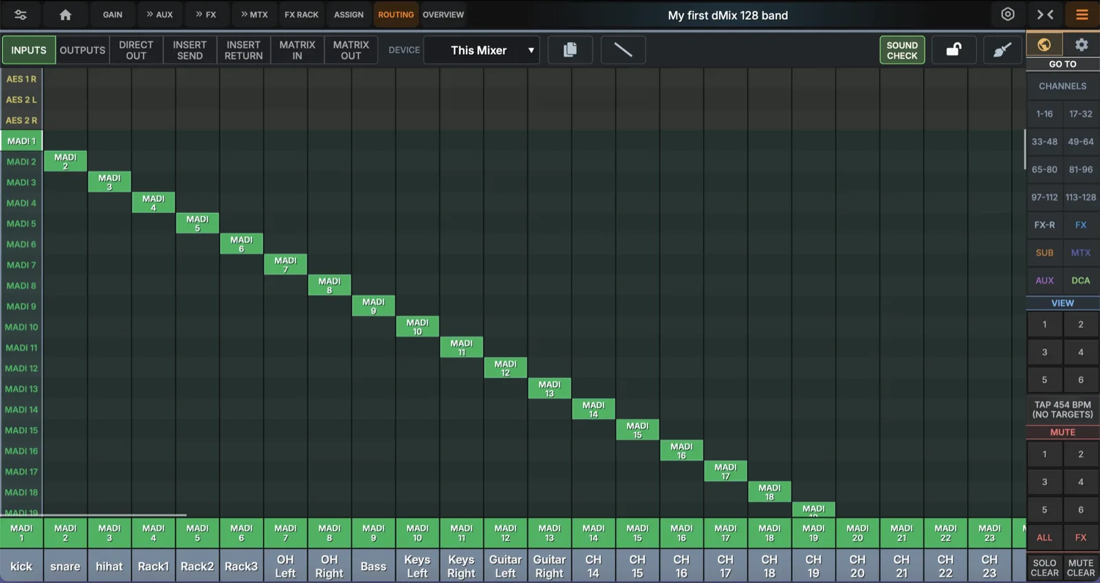
Routing - Inputs
The patch page maps physical inputs to channels and bus outputs to physical/digital outs. The console exposes hardware analog (XLR), AES, MADI (64ch), expansion (64ch) and headphone outputs as well as other connected devices— every output is freely assignable.
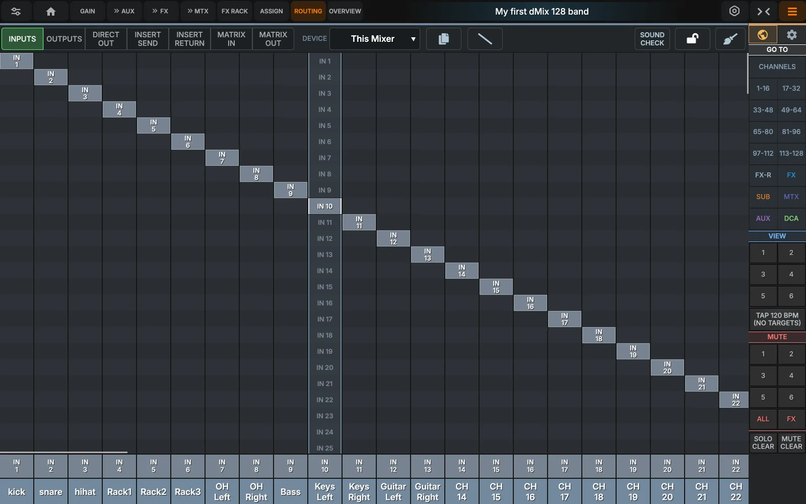
- Hardware inputsThe 32 analog XLR inputs can be assign to any channel from the Source picker. Defaults: inputs 1-32 local XLR. 2 AES ports are also available to select from.
- MADI / EXP gridEach cell is one channel of the 64-ch MADI or expansion stream. Tap a cell to assign; rubber-band-select to bulk-assign.
- Source selectSelect from the Local IO or externally connected IO
- SoundcheckAssign IO for Soundcheck mode (generally to external MADI or connected computer)
- Copy channelsCopy a set of channels with Prefix and Routing for an easy way to setup a monitor section in the mixer.
- Cascade assignSelect first channel and the number of channels for a fast cascade routing option.
- DefaultResets selection to default (Local 1-32)
Routing - Outputs
Write the introduction here.
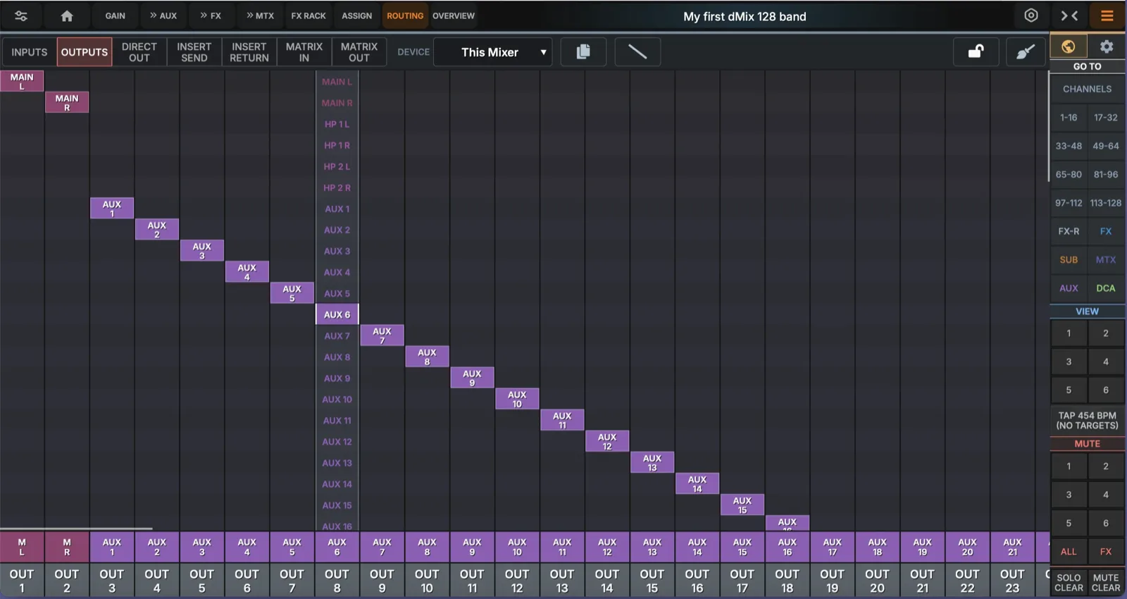
- Output RouteThe 24 analog XLR output can be assign to any bus from the Source picker. Defaults: outs 1–2 = master L/R; outs 3–24 = aux 1–22.
- AES and HeadphonesTwo AES pairs and four phones outs are independently patchable. Phones default to the solo bus and the two cue buses.
- External connectionEach cell is one channel of the 64-ch MADI or expansion stream. Tap a cell to assign; rubber-band-select to bulk-assign.
- Select Local or Network outputMultiple output locations can be assigned for each bus, select form Local or externally connected devices.
- Defaultreset to Default settings.
- Direct outputSelect this page for assignment of DIRECT CHANNEL OUTPUT. setup mainly for recording or a direct feed of timecode as an example.
- Insert Send/Return and Matrix IOSelect pages for routing inserts (can be done on the channel as well) and the Matrix IO.
Copy Channels for monitor split
When a copy of channels are needed (example: setup a complete copy of the input channels so you have a monitor setup ready to go) use the Copy Channel icon in the routing page.
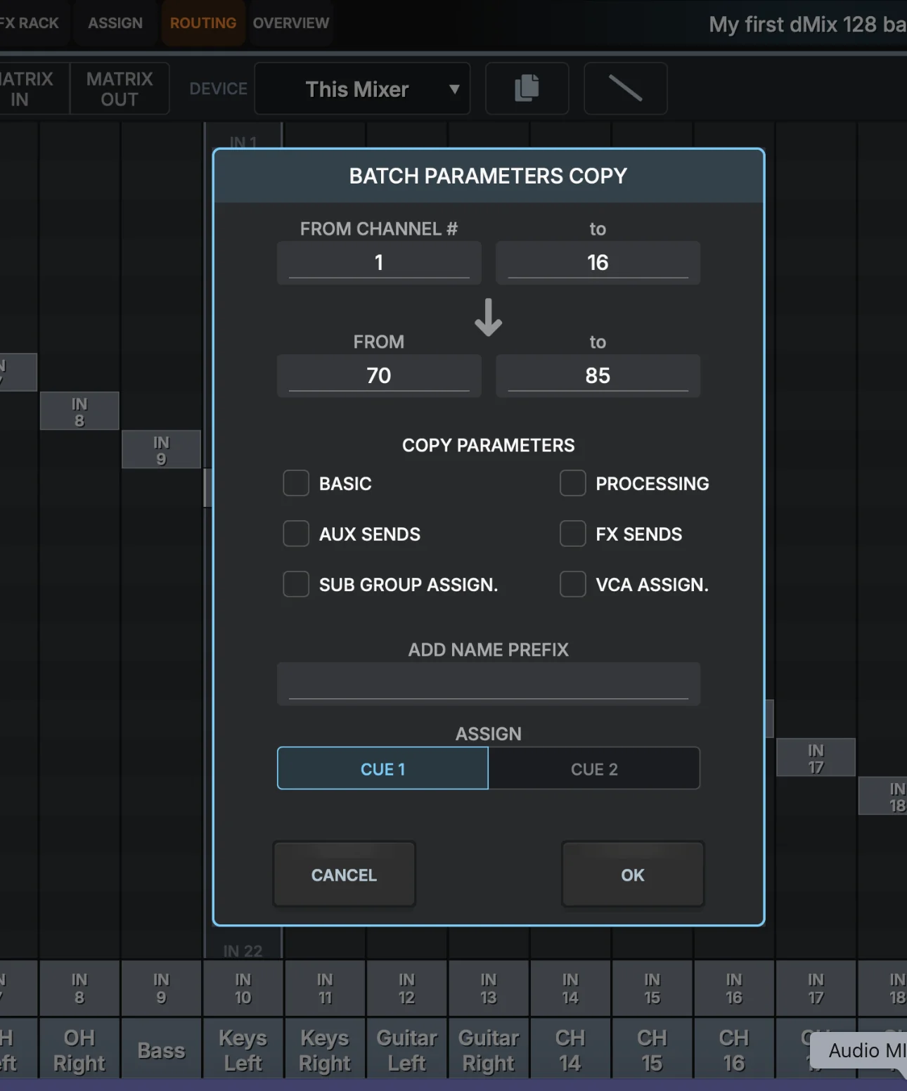
- Select start / end channelsSelect the start channel and how many channels you want to copy
- Select Copy to channelSelect the COPY START channel, the end channel will automatically be assigned.
- Copy ParametersSelect the parameters you want to copy, for example a monitor mix would just use the BASIC settings to copy routing
- Name PrefixAdd a prefix to the name. IE: MON- , the first channel will then me MON-Kick if your channel one was called Kick. Massive time saver.
- Cue selectAssign all channels copied to CUE1 or CUE2, great if someone else is adjusting monitors on a separate Cue output.
Cascade assign channels
Fast assignment of channels in a cascade manner
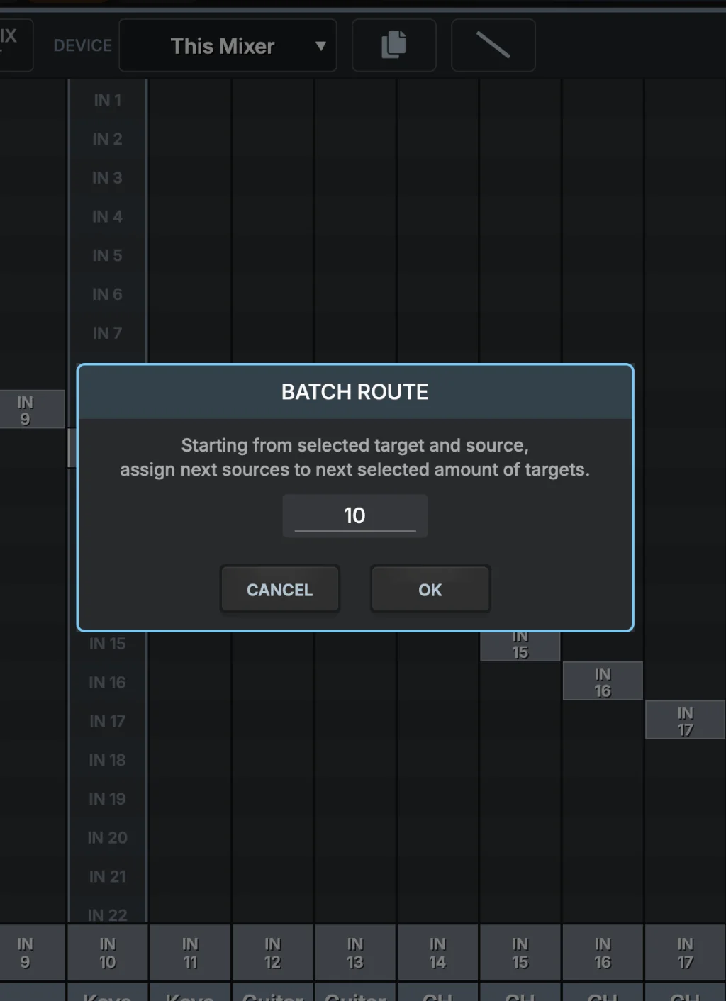
- Cascade assign selectClick to select this function, make sure you select the first channel in the Routing page before selecting this function
- ChannelsEnter the number of channels and click OK
Soundcheck Mode
SoundCheck Mode lets you play back previously recorded multitrack audio through the mixer as if the performers were live on stage. It is Used to check settings, adjust EQ, dynamics, effects, and monitor mixes without needing the band to be preset. It can also be used for alternative routing with a single press of a button. Activate the SOUND CHECK button and route inputs to your destinations from any connected device or the dMix 128 hardware inputs themselves. You can SWITCH SOUNDCHECK Mode on from the right hand panel's second settings menu.
- Activate Sound Check RoutingTurn on the routing page for Soundcheck selection of Inputs.
- Unlock Routing pageUnlock/ Lock Routing
- Cascade RoutingRoute n-to many in cascade.
Users can forget they are in Sound Check Mode and think that the mixer is not receiving any inputs, a real GOTCHA in some situations.
DCA, SUB, mute & view groups
One page where all internal assignments can be seen for fast selection and programming. Left Right assign, DCAs control level on multiple channels with one fader. Mute groups mute many channels at once. View groups bring sets of strips onto a custom bank for fast access, SUB are subgroups, Colours - assign to channels. Cue selection. These selections can be performed individually on inputs and outputs as well.
- DCA stripsEach VCA looks and feels like a regular fader/meter strip. Drag any input strip onto a VCA tile (or use ASSIGN) to add it; the channel's fader inherits an additional offset from the VCA.
- LR assignAssign or remove channels from master bus outputs
- Mute groupsMute groups light up red when active. The mute-group mask is one bit per group, so a channel can belong to several mute groups at once.
- View groupsView groups define which channels are visible on a custom user layer (6 view groups per user). They affect display only — never audio. They are stored locally in each persons browser.
- Sub GroupsAssign channels to one or multiple sub groups(note by default when a channel is assigned to a SUB, it is removed from LR, you can re-connect it if you want but be aware of doubling up your sound)
Internally each channel stores a 6-bit mgmask indicating which mute groups it belongs to. Bit 0 = MG1, bit 5 = MG6. The Edit button on a mute group enters mass-assign mode where you tap each channel to toggle membership.
DCA Remote Faders
A DCA lets you control the level of multiple channels at the same time without actually routing their audio through that fader. For example you could assign all drums to DCA1 and relative levels of all faders would be controlled together. DCA does not pass audio. the dMix 128 has 16 DCA's.

- SpillShow a mixer page with all the channels assigned to a given DCA. Example if drum channels are assigned to DCA1 then pressing spill will open up a mixer page with just the drum channels to edit.
- EditEdit which channels are assigned to this DCA. Assignments of channels can be done in 3 ways. On the channel itself, in the DCA or in the Assign main page.
- Solo DCANot a common function on many consoles but SOLO DCA will listen to a mix of what is being controlled on the selected DCA.
- DCA VUA vu meter, showing an average of the signal the DCA is controlling, as no audio passes through the DCA, this is more of an indicator than a real value but it gives the mixing engineer an indication that audio is being controlled and the average level of the audio signal.
- DCA MuteMute the DCA and all the channels it is controlling.
- NamingClick and Hold to rename DCA and change colours. Assign to View groups or Cue's.
Sub Groups
The dMix 128 has 12 assignable sub groups.

- Open processing pageClick to open all the processing options for the subgroups, EQ, compression, Inserts etc.
- Sub Group SOLOSolo listen to each subgroup
- Sub Group MuteMute each subgroup
- Naming/colours/AssignClick and Hold to open the sub menu for naming and assignments.
Matrix Mixing
The dMix 128 has a 12 channel x 8 send Matrix mixer. Each Matrix channel can be selected from any channel in the mixer including Subgroups/Aux/inputs/FX.
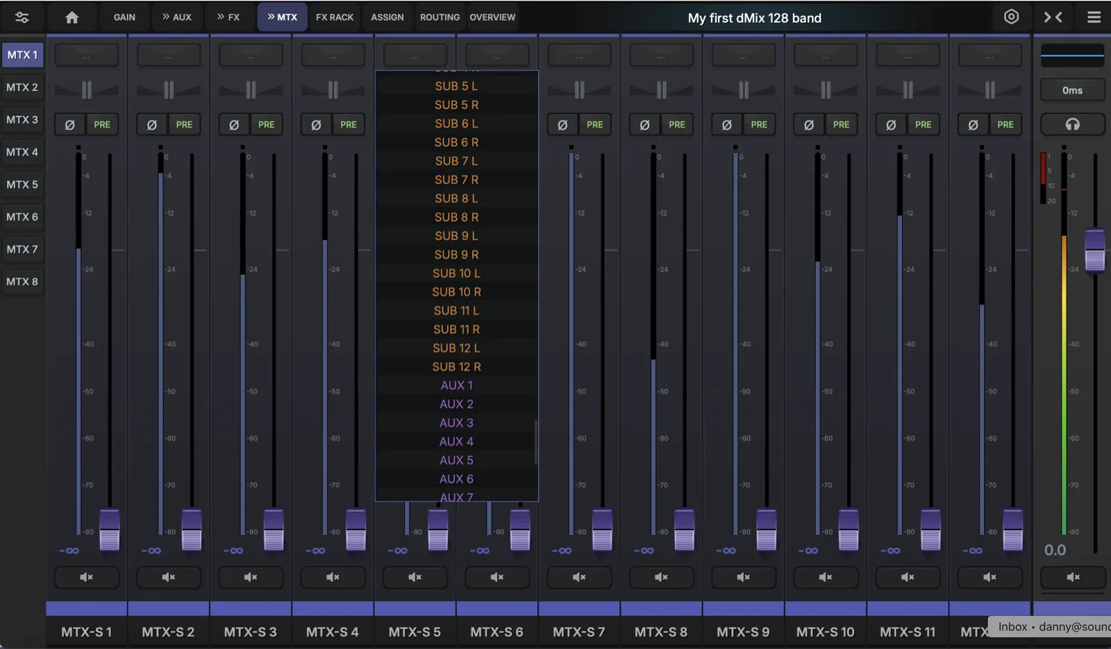
- Matrix input selectSelect where an input is being assigned from to a Matrix channel.
- Matrix input pointPre/post or Pre Processing can be selected
- Phase reverseReverse the phase by 180 degrees
- PanIf a Matrix is Linked to another Matrix, the PAN control will be enabled.
- Output DelayAdd delay to the Matrix output
- ProcessingAdd EQ, Compression, Inserts
- Matrix MasterSelect which Matrix is being edited
Use a matrix as a final "output control" stage for different speaker zones or feeds. Matrix 1 in stereo for Left and Right Main PA, Matrix 2 mono for From fill, maybe with HPF EQ. Matrix 3 for Sub woofer control, Matrix 4 for Delays . Matrix 5 in stereo for LR record bus.
Shows & snapshots
The show system organizes your mix into named collections called shows, each containing multiple snapshots. A snapshot recalls the entire state of the mixer — channel names, processing settings, sends, VCA assignments, and more.
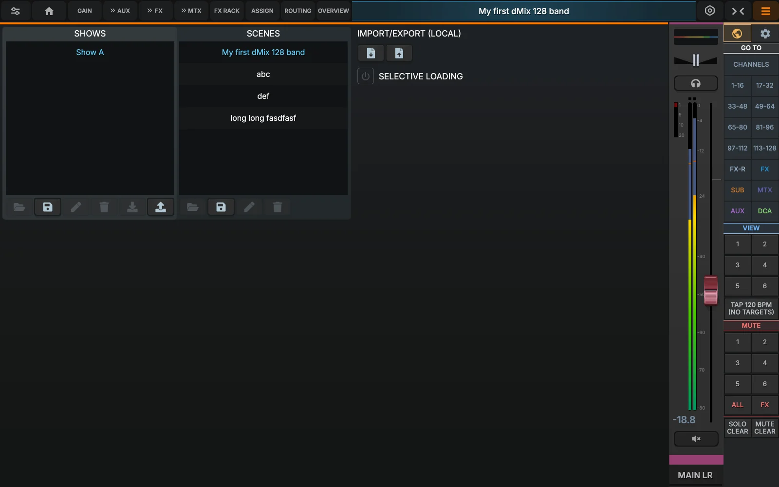
- Show libraryEach show is an independent collection of Scenes. Shows can be loaded, saved, renamed or deleted. The active show is highlighted and marked as LOADED.
- Scene LibraryUp to 99 Scenes per show. The current Scene is highlighted amber. Empty slots appear dimmed. Each Scene stores the complete mixer state.
- Scene/ show SaveClick this Button to SAVE the scene. Selecting a Scene will overwrite it!
- Scene / show LoadClick this button to Load a scene (a warning will be display that you will overwrite the current mixer state) Using Snapshot RECALL NEXT button can over-ride this warning in the Settings page.
- Scene / Show RenameRename currently selected Scene or Show
During setup, store snapshots after each major change (per-song adjustments, intermission levels, guest vocalist settings). Name them clearly and add notes. During the show, single-tap recall switches instantly; there's no confirm step to slow you down. (can be setup in the settings page)
Scene Isolation
Scene isolation controls which parts of the mixer are recalled when you load a snapshot. With isolation engaged, you can recall just the EQ settings from snapshot A while keeping the current fader levels and sends intact.
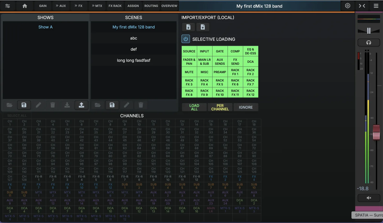
- Isolation on/off
When isolation is disabled, snapshot recall replaces the entire mixer state. When enabled, only the checked parameters are recalled from the snapshot; unchecked items keep their current values - Parameter categoriesIsolation works at a granular level. You can isolate just the EQ settings, just the compressor, just the input routing, etc. Each parameter group has its own checkbox.
- Channel specific ParametersEvery channel type (input, aux, FX, sub, matrix) can have different isolation rules. Use this when you want to recall EQ on vocals but leave the drum processing untouched.
- Channel SelectorApply isolation rules to all channels, or filter by channel type. The SELECT option lets you hand-pick specific channels for isolation.
Set isolation to recall only EQ + compressor on input channels. Now when you switch between songs, the snapshot loads new processing but keeps the current fader levels and send amounts. Perfect for festivals where the band changes but the FOH engineer stays put.
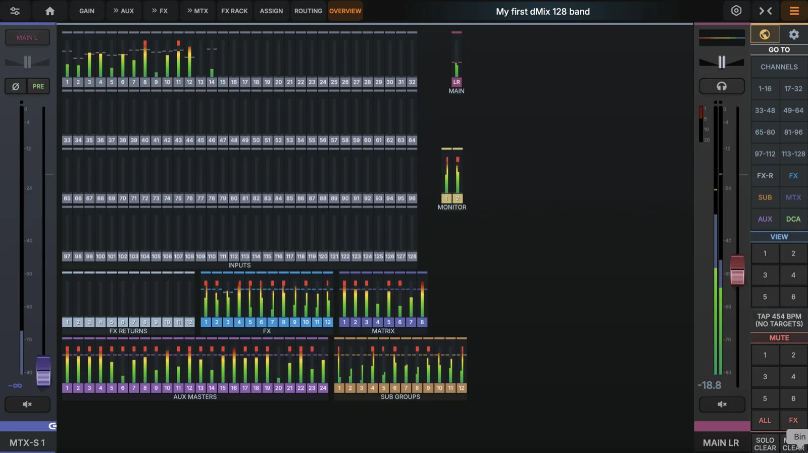
Overview Page
See all inputs and all outputs, click on a channel to take you to it's main edit page.
- Callout 1Description.
Presets
Presets save individual processing blocks — EQ curves, compressor settings, gate timings, FX parameters — for quick recall across channels and shows. Unlike snapshots which store the entire mixer state, presets focus on one processor at a time or a complete Channel strip
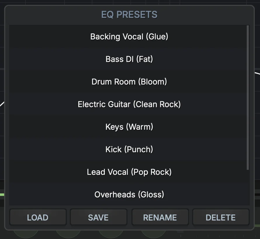
- Processor typesPresets are organized by processor: EQ, compressor, gate, graphic EQ, de-esser, FX and multiband compressor. Each type has its own preset library with factory defaults plus user-created presets.
- Preset descriptionsEach preset shows a human-readable summary of the settings. For EQ presets this includes the key frequency points, gains and Q values. Compressor presets show threshold, ratio and timing.
- Load/Save/Rename/DeleteLoad a preset onto the currently selected channel. Use save to save the current processor settings as a new preset. Rename presets and Delete a Preset.
Factory presets are protected from accidental modification and provide sensible starting points for common instruments. User presets can be renamed, deleted or overwritten. Use the IMPORT button in the main settings page, to bring in preset libraries from other dMix 128 consoles or export your own. Initially your dMix128 won't have any presets in it.
Oscilator
The built in Oscillator audio can be sent to any channel or output. Select between PINK NOISE and SINE WAVE, vary the frequency and level.
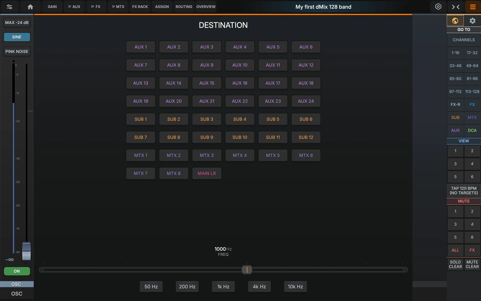
- Select Type and MAX levelSelect between sine wave and Pink Noise and MAX level
- Select FrequencySelect the Frequency of the oscillator when in Sine wave mode
- Select routingSelect where the oscillator will be routed to
Enable EQ overlay, then boost or cut EQ bands while watching the spectrum. You can see exactly which frequencies you're affecting and verify that problem frequencies are actually reduced. Use FREEZE to capture a problem moment for detailed analysis.
Shortcut Keys
Quick reference for short cut keys:
Use these tables when building custom control surfaces or integrating with lighting/video systems. Channel names follow the pattern TYPE.NUMBER.PARAMETER, e.g. h.5.gain for input 5 preamp gain (preamps live in the h.* namespace), or a.2.mix for aux 2 level.
Adding Network devices -1
The dMix 128 AES67 setup page will show all devices that are connected to the dMix 128 network. 4 other hardware units and 2 computers can connect to the dMix 128 at the same time currently. (this will be expanded with future firmware versions and not a restriction of hardware).
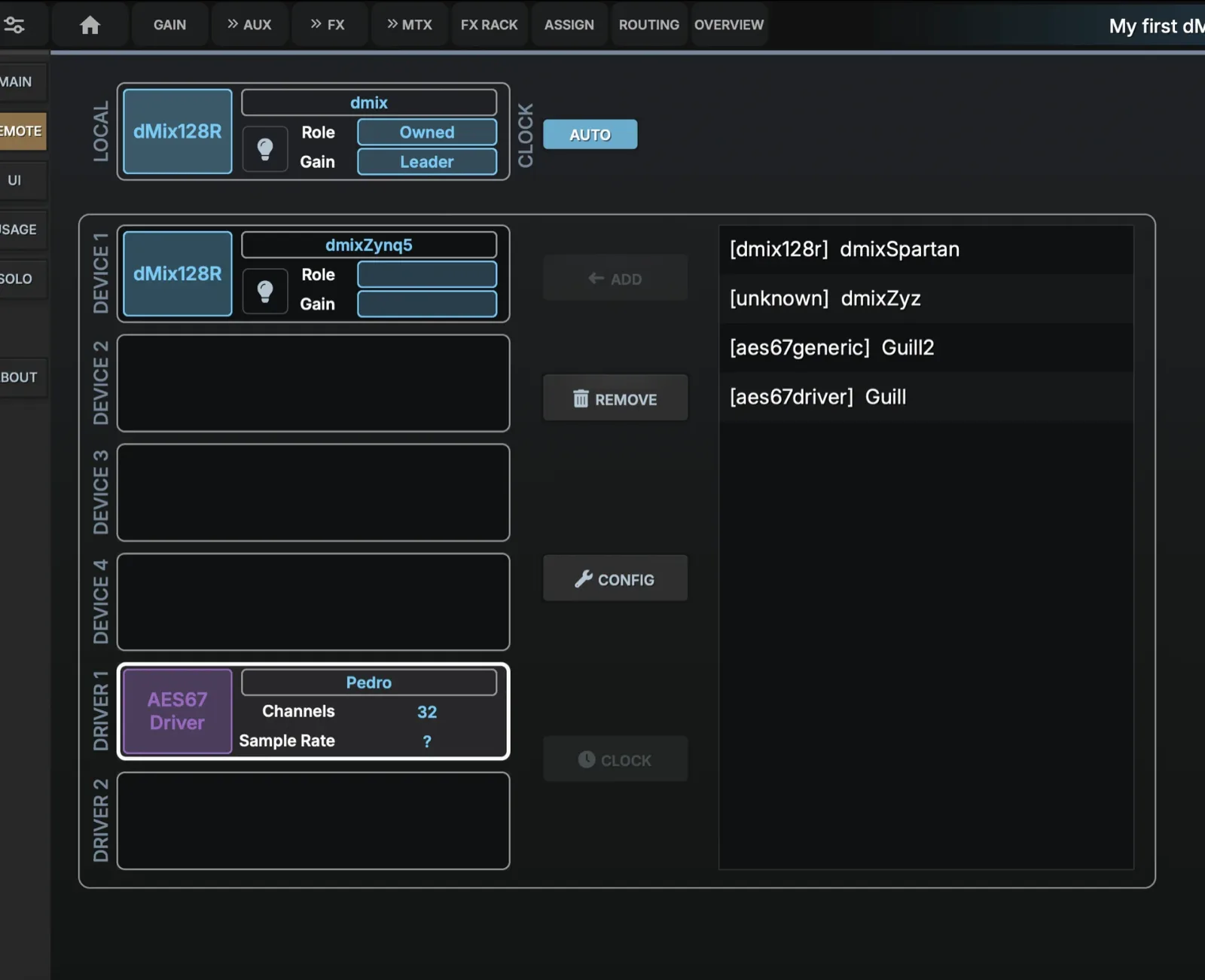
- Computer connectedShow computer name connected, any computer that has the dMix 128 AES67 driver will show up in the list. Up to 2 Computer devices can be added at the same time for recording or playback of audio.
- Configure connectionSelect the sample rate and how many channels the AES67 stream is going to use
- Remove connectionRemove any connected device.
- AES67 GenericSome Generic AES67 devices can be connected directly to the dMix 128. A full list of devices will be available on the Violet Audio website. (for example Dante devices that can transmit AES67 once setup in Dante Manager)
- Other dMix hardwareOther hardware will appear on this list as well, up to 4 hardware devices can be connected at the same time.
Once connected, open the patching screen and select the device you want to PATCH to/from.
adding devices -2
Connected hardware devices will appear on the right side Panel
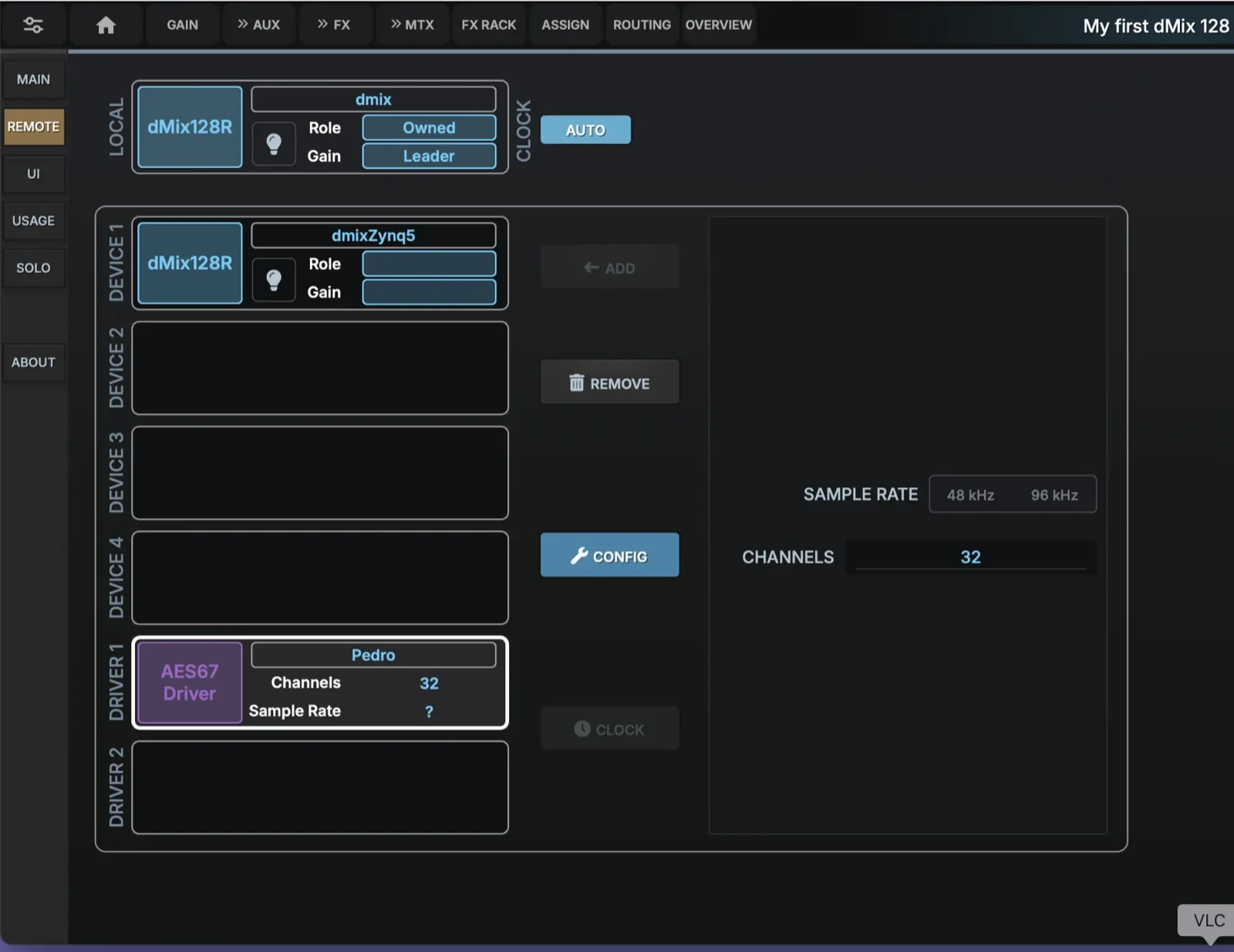
- Role and Gain sharingSelect the Role of each connected device directly on their own page (Follow Gain or Leader, Owned or Shared device). If a device is OWNED no other device can control its Gain, if a device is shared it can be remote controlled for audio IO.
- Connected HardwareA connected device will show its state and the Show file can save its connection information for later recall. Be aware that changing the connected device will reset any connections to it.
- Configuration pageSelect Sample Rate and Channels for each connected device. The system has an internal clock of 96kHz and Sample rate conversion for any input that is at 48kHz.
The function of each connected dMix 128 hardware unit (Owned/Locker or Leads/Follower ) needs to be selected on the Gui of the unit itself. When multiple units are used name the DNS GUI name with a different Name, IE dMix1. local dMix2.local etc. Otherwise you won't be able to communicate with them unless you know the IP address.
Ui Page
Write the introduction here.
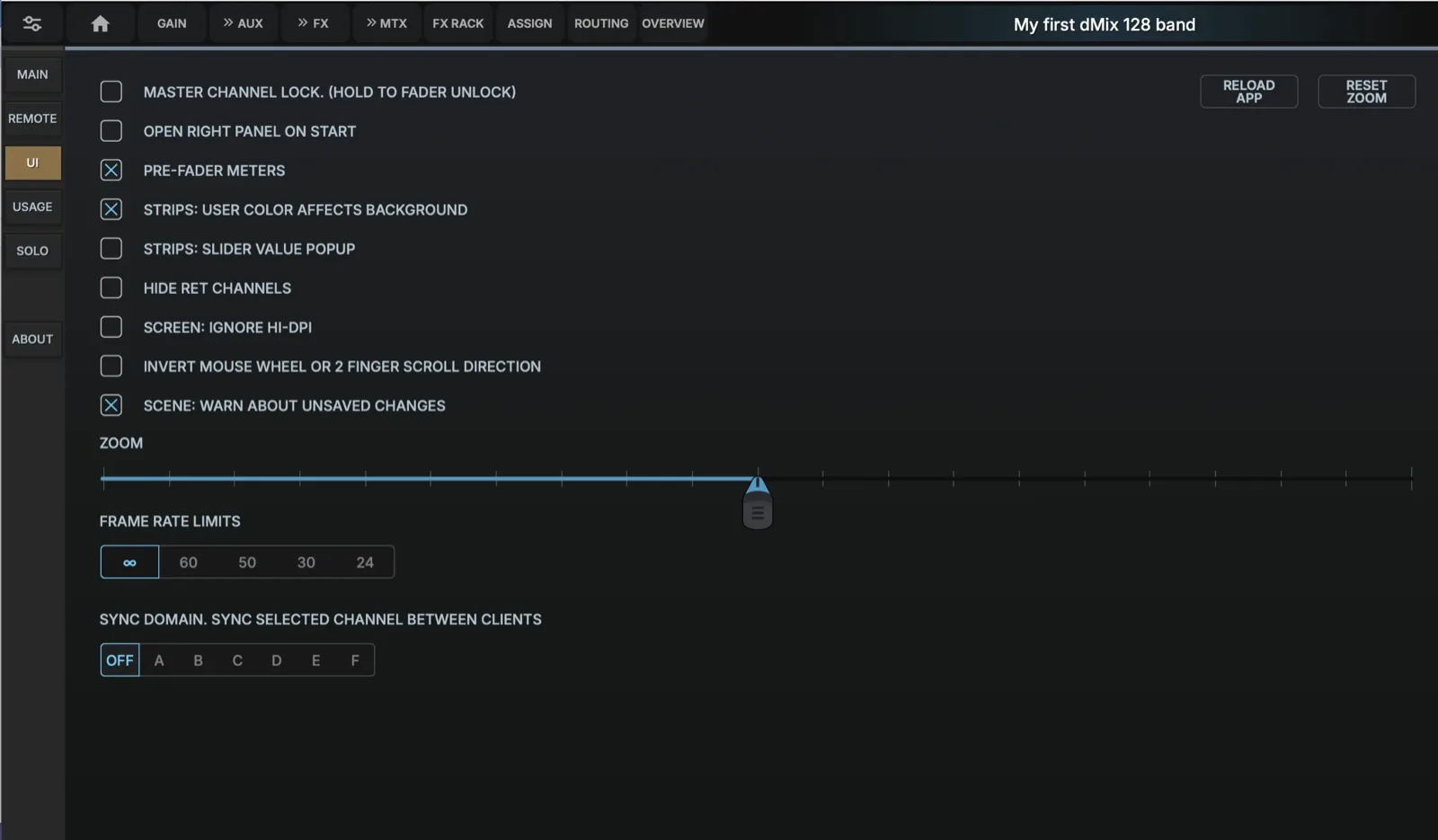
- Master Channel LockLock the Master Fader so it can't be moved easily. (hold down for 1 second to change it's value)
- Right Panel openOpen Side Panel automatically on mixer display
- Pre Fader MetersThe Channel Meters can display Pre Fader Meters or Post Fader Meters, by default they are Post Fader. The Channel also displays GAIN/INPUT level as well as OUTPUT level.
- User Colour EffectsSelected channel strip highlights
- Slider Value PopupWhen slider value are changed a pop up will appear
- Hide Return ChannelsHide FX return channel on the FX pages
- Ignore High DPISpeeds up the GUI on slower systems
- Invert Mouse wheel or 2 finger useWant to use a different type of mouse?
- Scene: Warn about unsaved changesFast Scene change warnings
- ZoomBesides the Web browser zoon, the dMix 128 gui can be zoomed to scale and fit into practically any device.
- Frame RatesFor slower processors
- Sync DomainHave multiple browsers across a network communicate together to achieve a control network. Have one page on EQ, one on Compressor, As you select faders on a third they will all sync up.
Processing usage
This page displays all the internal processes that have limits and where they are allocated.
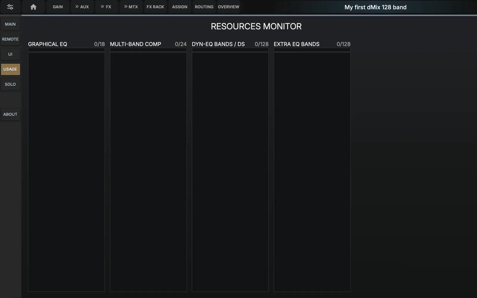
- Show processing usageShows which channels are using internal processing and how much of it remains
- Channel in useClick on the channel that uses the specific process to free it or edit it.
If you try to enable a precess , (EG 19th Graphic EQ) on a channel and it won't let you turn it ON, you can free up a slop by turning off the process in another channel.
Solo
The dMix 128 has 2 Solo/Cue busses, each with their own settings.
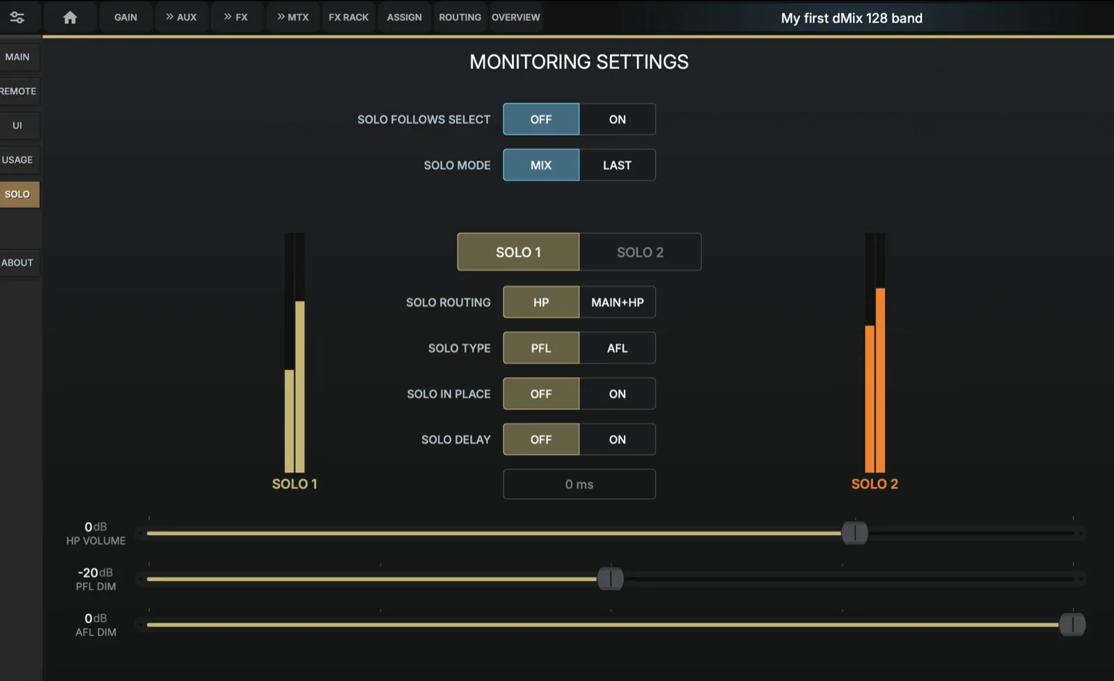
- Solo Follows SelectThe Solo output (1 or 2) will always follow the selected channel or output bus automatically. Enable follow select to automatically solo any channel you're editing. This is especially useful when dialing in EQ or compression — the channel solos as soon as you open its processing panel, giving you instant isolated playback.
- Solo ModeMix (several channels can be soloes and mixed), Last (Last pressed SOLO is the one in use)
- Solo RoutingHeadphone Only or HP and Main output
- Solo TypePFL (pre-fader listen) hears the channel before the fader, perfect for checking input sources. AFL (after-fader listen) includes the fader level and is better for checking the final mix contribution. AUTO uses PFL for input channels and AFL for auxes and groups.
- Solo In PlaceWhen ON, pressing Solo will Mute all other channel to the master output
- Solo DelayAdd delay to the Solo output
- Output VolumeHP output level, PFL Dim, AFL Dim
The Solo output can be routed to speakers as well as the headphones. Be aware in a Live gig not to output SOLO to the main speaker output! In a studio you often want to do that but keep the PFL and AFL levels lower.
About
Write the introduction here.
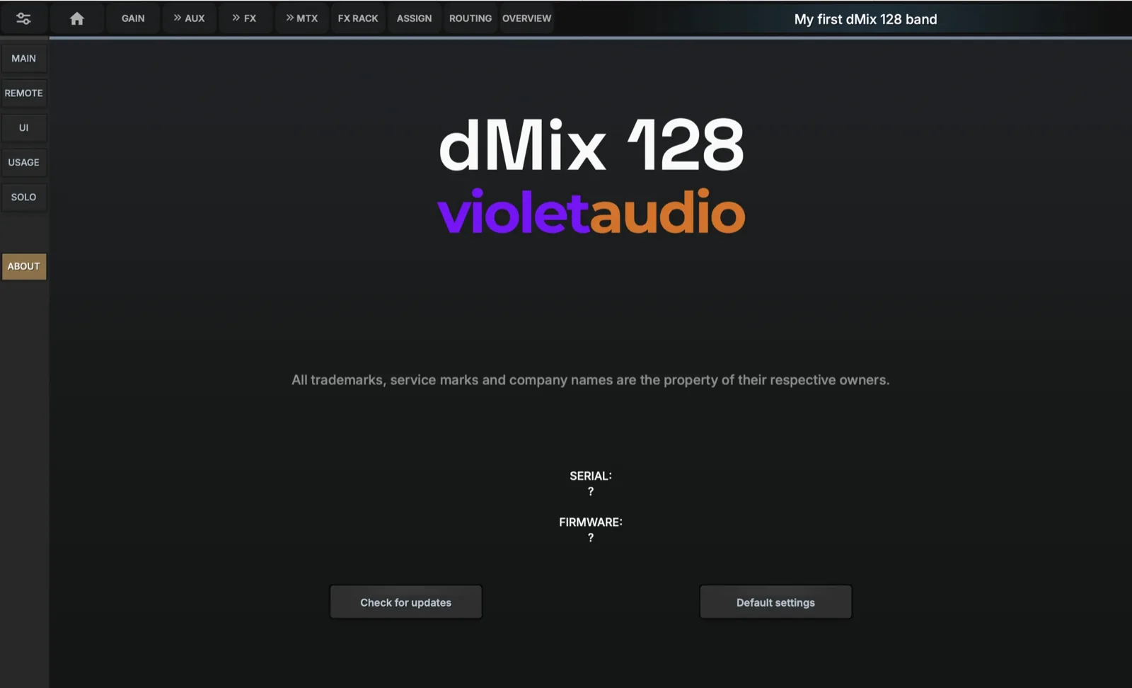
- Serial number and Firmware versionDisplays the dMix 128's serial number and firmware version. Important when asking for any support or performing system updates.
- Check for updatesIf the dMix 128 is connected to the Internet, the system will check against current firmware for any updates.
- Default settingsErase all internet current show settings and routing. (all saved data does not get affected)
Firmware update & Recovery Options
The dMix 128 has several ways to recover if a user forgot a password or a network setting. It can also assist in firmware updates. Violet Audio website has several documents showing recovery process and connectivity information.